What Are the Key Considerations for Automotive Tube Components Manufacturing?
Global automotive fluid systems market by 2029
Tube and fluid line components per modern vehicle
Of field failures traced to fluid line and tube component issues
Why Tube Component Manufacturing Is More Complex Than It Looks
Tube components are the circulatory system of the modern vehicle — carrying fuel, coolant, brake fluid, hydraulic pressure, and exhaust gases through environments that demand dimensional precision, chemical resistance, and fatigue durability simultaneously. For OEM engineers and procurement teams, understanding what makes a tube component supplier genuinely capable starts long before an RFQ is issued.
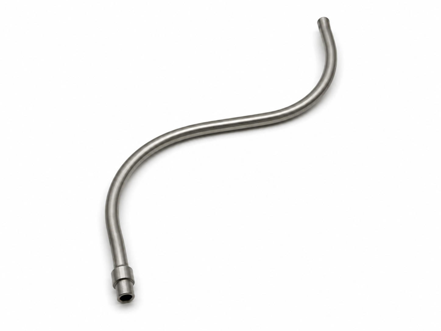
To the untrained eye, a tube component looks simple: a formed metal or polymer conduit connecting two points in the vehicle. In reality, every automotive tube component is a precision-engineered product operating under a combination of pressure, temperature, vibration, and chemical exposure that demands careful material selection, exacting dimensional control, and a rigorous quality system to ensure nothing fails in service.
The stakes are significant. A brake line that loses pressure integrity is a safety event. A fuel line that cracks under thermal cycling is a fire risk. A coolant tube that fails at a fitting under vibration fatigue is an engine damage event. In each case, the failure mode was determined not by bad luck but by a manufacturing decision made earlier in the supply chain — a material grade not properly validated, a bend radius that induced residual stress, a fitting that wasn't leak-tested under representative conditions.
This is why OEM procurement teams and engineers need a clear understanding of what separates a capable automotive tube components manufacturer from a generalist metal fabricator quoting on tube work. The gap between those two descriptions is the gap between a reliable vehicle and a warranty claim. For teams already thinking about how process selection affects component performance, our guide to CNC machining vs forging for automotive parts covers the broader process decision framework.
"Every tube component in a vehicle is quietly doing a critical job. The manufacturing decisions made upstream are the only reason it keeps doing that job through 10 years and 150,000 miles."
The Tube Component Landscape: What Gets Manufactured and Why It Matters
Before examining the key manufacturing considerations, it helps to map the full scope of what an automotive fluid handling components supplier is expected to produce. The modern vehicle contains a dense network of tubes, lines, and fluid-carrying assemblies spanning multiple systems, each with distinct material, pressure, and environmental requirements.
- ⇒Brake lines and hydraulic tubing operate at 100–150 bar in normal braking, with spike pressures significantly higher under ABS actuation. These lines are almost universally double-wall steel (Bundy tube) or stainless steel, with zinc-nickel or polymer coating for corrosion resistance.
- ⇒Fuel lines and fuel rail components operate in a chemically aggressive environment — modern direct injection systems run fuel at 150–350 bar, and the fuel itself attacks certain polymers and coatings over time. SAE fuel system standards govern every design decision.
- ⇒Coolant and HVAC tubing operates at the widest temperature range of any fluid system, from -40°C cold starts to 130°C in sustained operation. Thermal cycling fatigue and electrochemical corrosion at aluminum joints are the dominant failure modes.
- ⇒EGR and turbocharger intercooler tubes add high-temperature stainless steel and thermally resistant aluminum alloys, operating where thermal distortion, vibration fatigue, and pressure pulsation combine in the most demanding way.
- ⇒Battery thermal management tubes (EV) carry glycol coolant through lithium-ion battery packs and add tighter dimensional tolerances and higher leak integrity requirements than any previous fluid system.
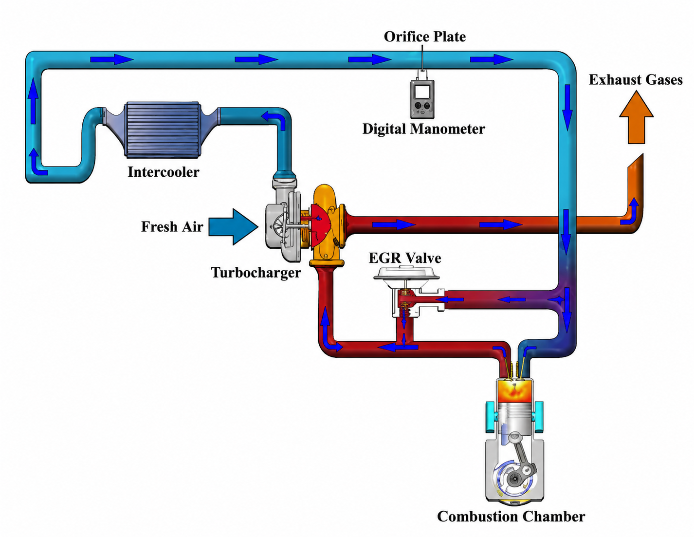
A schematic diagram of EGR System by Mohamed Gomaa. All rights are reserved.
Key Considerations When Sourcing from a Tube Components Manufacturer
Whether you are qualifying a new custom automotive fluid carrying components supplier or re-sourcing an existing tube component family, the following considerations define the evaluation framework. These are not generic quality checklist items they are tube-specific capability requirements that a fabrication generalist cannot fake their way through an auidt day.
Material Selection and Compatibility Expertise
The right tube material for each application is not always the obvious one. Double-wall steel Bundy tube has been the brake line standard for decades, but stainless steel is increasingly specified for corrosion-intensive environments. Aluminum alloys offer excellent weight and corrosion performance for coolant and HVAC lines but require careful alloy and temper selection to avoid intergranular corrosion at fittings. Nylon PA12, PTFE-lined hoses, and thermoplastic elastomers each have specific chemical compatibility windows — and using the wrong polymer against certain fuel blends or coolant additives produces silent, progressive degradation rather than immediate failure.
A capable automotive metal parts manufacturer in the tube space will maintain a material selection database cross-referenced against fluid compatibility, temperature range, regulatory compliance (particularly REACH and RoHS for coatings), and OEM-approved material specifications. This is not a capability that can be developed in response to a specific RFQ — it exists before the enquiry arrives, or it does not exist at all.
Tube Forming and Bending Process Control
Most dimensional and structural failures in automotive tube components originate at bends, flares, and formed ends — not in the straight runs. This makes the bending and forming process the most critical manufacturing operation for any tube component supplier to control well. Rotary draw bending with mandrel support is the standard for tight-radius bends in steel and aluminum tube, but the process requires precise control of bend angle, spring back compensation, wall thinning at the extrados, and ovality — all of which should be subject to Statistical Process Control with Cpk targets of 1.67 or above on critical dimensions.
End forming — flaring, beading, and swaging — is equally critical. The flare geometry on a brake line end fitting determines the leak integrity of the connection across the entire service life of the vehicle. A flare angle that is 2° out of specification may pass an initial leak test but will generate a fatigue crack at the sealing interface after several years of vibration and thermal cycling. Leading automotive components suppliers validate end form geometry with dedicated gauging on every production piece — not sampled inspection.
Coating, Surface Treatment, and Corrosion Protection
The corrosion protection system on a steel brake or fuel line is not cosmetic — it is structural. Automotive tube components are routed through the underbody of the vehicle, where they are exposed to road salt, water, stone impact, and the full spectrum of automotive fluid contamination for the entire vehicle life. A tube that meets dimensional specification on day one but corrodes through in year three is a product liability event, not a warranty statistic.
Zinc-nickel electroplating has largely replaced zinc and cadmium as the preferred corrosion protection for steel brake lines, offering 1,000+ hours of neutral salt spray resistance in a thinner, more consistent coating that does not interfere with flare geometry. Nylon over-coating (PA12 or PA11) provides additional physical and chemical protection on fuel lines in particularly aggressive environments. A qualified automotive tube components manufacturer must demonstrate validated coating process control, regular salt spray testing to SAE J2547, and full lot traceability on coating chemistry and bath parameters.
Leak Testing and Pressure Validation
Every finished tube component that carries brake fluid, fuel, or coolant must be leak-tested — no exceptions, no sampling. This is not an audit requirement; it is a physics requirement. A leak that is too small to affect an initial flow test will propagate under pressure cycling and thermal fatigue into a service failure that is expensive, dangerous, or both.
The testing method matters as much as the requirement. Helium mass spectrometry leak testing detects leak rates as low as 10⁻⁹ cc/sec and is the OEM standard for brake lines and high-pressure fuel components. Pressure decay testing is appropriate for lower-criticality coolant and HVAC lines. Air-under-water testing cannot reliably detect the micro-leaks that cause progressive field failures. A serious automotive components supplier specifies the testing method based on the application's leak integrity requirement — not based on what equipment they happen to own.
The Four Manufacturing Capability Pillars Every Tube Supplier Must Demonstrate
General certification is insufficient. The scope must explicitly cover tube forming, end forming, coating, and assembly processes at the production site.
Level 3 PPAP minimum — DFMEA, PFMEA, control plan, MSA study, and initial capability study with Cpk ≥ 1.67 on all critical bend, flare, and coating dimensions. Request from a comparable prior program before selection.
Helium mass spectrometry for brake and fuel lines, validated pressure decay for lower-criticality applications. Sampling-based leak testing is not acceptable for safety-critical tube components.
Full heat and lot traceability on tube material, coating chemistry, and assembly hardware retained to support recall investigation if required. Conflict mineral compliance documentation required for all metallic inputs.
Tube Component Applications and Manufacturing Requirements at a Glance
| Application | Typical Material | Critical Manufacturing Requirement | Risk Level |
|---|---|---|---|
| Brake Lines | Double-wall steel (Bundy), stainless steel | Helium leak test, flare geometry validation, zinc-nickel coating | Safety Critical |
| High-pressure fuel rail | Stainless steel, high-strength steel | Burst pressure test, 100% helium leak test, surface finish on injector bores | Safety Critical |
| Low-pressure fuel lines | Nylon PA12, PTFE-lined, steel with nylon overcoat | Chemical compatibility validation, permeation testing, fitting pull-out force | High Precision |
| Coolant tubes (aluminum) | Aluminum alloy (6061, 6063) | Thermal cycling fatigue test, joint corrosion validation, pressure decay leak test | High Precision |
| EGR/turbo intercooler | Stainless steel, heat-resistant aluminum | Thermal distortion qualification, vibration fatigue test, weld integrity inspection | High Precision |
| Battery thermal mgmt. (EV) | Aluminum alloy, reinforced polymer | Ultra-low leak rate, glycol compatibility, dimensional precision at manifold interfaces | Safety Critical |
| HVAC refrigerant lines | Aluminum, multi-layer flexible hose | Refrigerant permeation test, fitting torque-to-leak validation, thermal range test | Standard |
EV Platforms and the New Demands on Tube Component Manufacturing
Electric vehicles are reshaping tube component requirements in ways that most legacy fluid system suppliers are not yet fully equipped to address. Battery thermal management is the most significant new system — lithium-ion battery packs require precise, uniform coolant distribution through aluminum or polymer tube networks that must maintain consistent flow rates, near-zero leak rates, and dimensional stability across the battery pack's operating temperature range.
The leak integrity requirements for EV battery thermal management tubes are stricter than any previous automotive fluid application. Where a conventional coolant tube leak test might accept a pressure decay of 0.5 kPa over 30 seconds, EV battery cooling circuits are increasingly specified to helium leak standards previously reserved for brake lines — because the consequences of glycol ingress into a battery cell are far more severe than a coolant top-up event.
Additionally, EV platforms eliminate the engine-driven vacuum source that powered brake boosters on ICE vehicles, moving to electrically assisted or hydraulic brake systems that introduce new fluid system architectures. For teams sourcing suspension and brake components alongside tube assemblies, this system-level change has flow-on implications for brake line routing, fitting specifications, and pressure rating requirements that must be addressed at the component sourcing level.
EV Sourcing Checklist
When qualifying a tube components supplier for EV programs, explicitly confirm the following:
- Leak test infrastructure meets battery-cooling circuit specifications — not just conventional coolant standards.
- Materials database includes glycol-compatible polymers and coatings validated for EV battery pack environments.
- Engineering team has experience with the thermal management system architecture on your specific EV platform.
- IATF 16949 scope explicitly covers EV thermal management tube assemblies, not only legacy fluid line families.
- PPAP capability study references a comparable EV battery cooling program — not a conventional coolant tube program.
- Dimensional verification process accommodates the tighter manifold interface tolerances common in EV pack architectures.
Sourcing brake, fuel, or thermal management tube assemblies? Talk to Marimba Auto's engineering team.
Get in touch →